
DIY Drift Kart: How I Built It
The story behind my Dad Drift Kart: designing a petrol drift kart in CAD, fabricating the frame and turning a pile of parts into something I could drive.

Designed and built in Melbourne, Australia
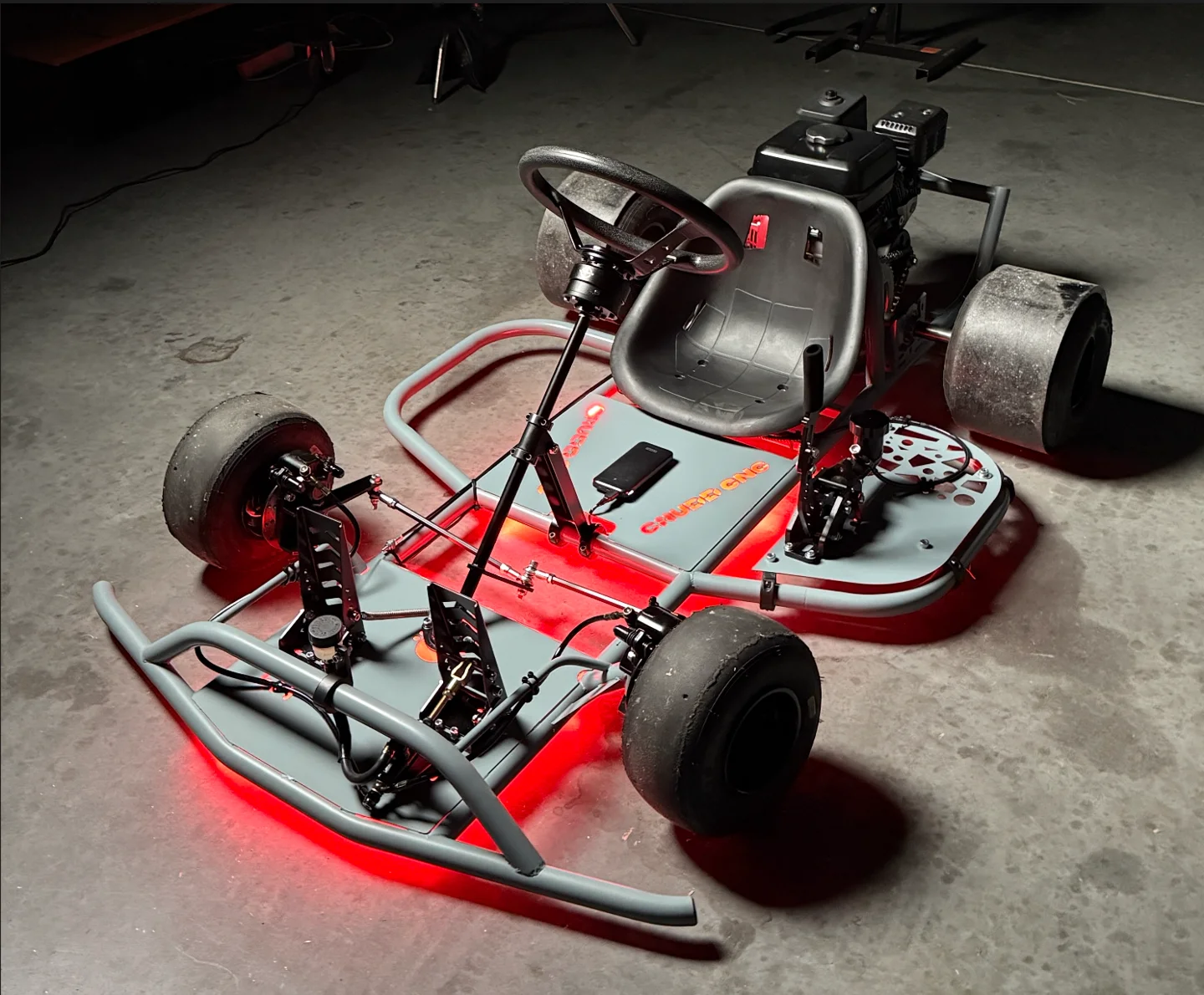
It started with my son’s drift car
After converting my son’s Cozy Coupe into a drift car, I started researching drift go karts. I wanted to see whether I could design and build my own. I wasn’t sure how it would turn out, but completing a bike and my son’s car had given me the confidence to have a go.
I couldn’t let him have all the fun. The idea of us drifting together stuck in my mind.
I started with a few A4 pages of sketches: angles, structure and possible layouts. Getting those ideas onto paper gave me the push to start modelling in Fusion 360.
Tools and workshop options
You don’t need to copy my workshop. This is what I used, along with alternatives. Tool and material costs vary considerably by country, supplier and whether you buy new or second-hand.
Tube bending
I used a tube bender for appearance and efficiency. An experienced fabricator could adapt the bent sections using mitred or pie-cut joints; that changes the fabrication approach and needs appropriate joint design and welding.
Welding
I used a laser welding machine. A suitable MIG or stick welder is another option, with the equipment settings and technique matched to the material and joint.
Cutting
An angle grinder with suitable cutting discs handles the cuts. A bandsaw or metal-cutting saw is convenient, but not essential if you have the grinder.
Spacers
I used a lathe to make some spacers. Suitable purchased spacers or washers can do the job where the dimensions and fit allow, so a lathe isn’t essential.
Templates and jigs
I used 3D-printed coping templates and alignment jigs. If you don’t own a printer, you can order the parts from a local printing service.
Paint and finishing
I painted my frame using locally available products. Powder coating is another option if you prefer to outsource the finish.
This is a fabrication project involving cutting, welding and mechanical assembly. The story below describes my build; use the drawings and component instructions for specifications.
For a reference parts budget and its inclusions, see the build cost breakdown. Your own sourcing choices will change the total.
The donor kart, CAD and parts that actually fitted
In the lead-up to Christmas, I found a go kart on Facebook Marketplace about two hours from home. I made an offer subject to inspection, and that weekend I was driving home with it in my truck. My justification was that I was buying discounted parts for my own kart.
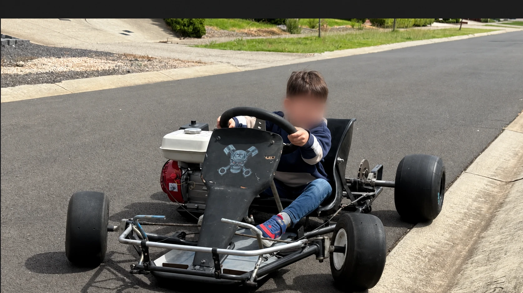
Now money had been spent, I had another reason to get moving. I fired up Fusion 360 and started measuring and modelling properly.
After several weeks of iterations and some frustrating CAD sessions, I had a design I was happy with. I thought ahead about fabrication: jigs, mitres and how I would stage the work. A rough spreadsheet helped, although the build still involved plenty of adapting as I went.
The donor kart turned out to be less useful than I had hoped. The rear axle, rear wheels and engine were useful, but its frame and steering components didn’t suit the drift geometry I wanted. I ordered additional parts from AliExpress while finishing the design.
Bending, cutting and tacking the frame
I bought lengths of tube from my local steel supplier and put the printed plans beside the workbench. A few test bends helped me get familiar with the bender before making the first two frame rails.
With the rails laid parallel on the bench, more cuts and mitres quickly made it look like a kart. The compound bends were trickier. I made mistakes and reworked sections as I went.
I initially tack-welded the frame so I could still reposition parts. I spaced the tacks around each joint to hold the components securely, checking alignment as the structure came together. Final welding came after the trial fit.
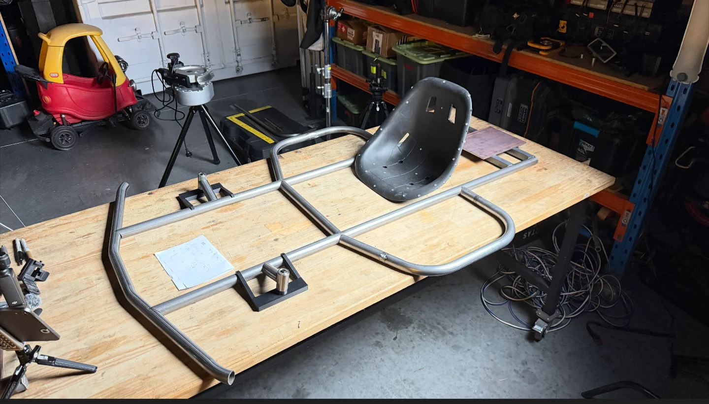
Steering mounts, printed jigs and the axle
The rear axle mounts came next, followed by the more demanding steering-knuckle mounting points. My 3D-printed coping templates and compound jig helped match the caster and camber angles on the left and right sides.
I touched up the tube ends for the bearing fit, then tacked the mounting points to the frame. As the video series shows, I later adjusted the front knuckle geometry to get the ride height where I wanted it.
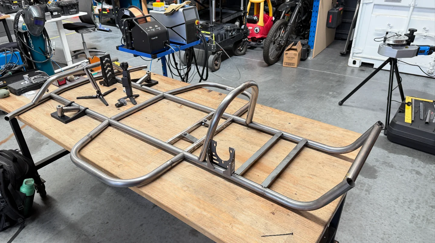
I added the seat rails, rear engine guard and front bar, which also provided a mounting location for the brake-fluid reservoir. The axle-bearing mounts and side bars completed this stage.
For the steering knuckles, I positioned the brake-caliper bracket with a 6 mm spacer. A spacer and nut also helped hold the axle bolt perpendicular to the knuckle while I tacked it in position.
On my build, the axle bolt was then welded around at least a quarter of its circumference on each of two opposite sides. It was not left attached by positioning tacks alone.
I also added a mounting point for the throttle cable on the left frame rail, using an M8 nut.
Trial assembly before final welding
With the parts tacked in place, I dry-fitted the components and checked that everything sat where I wanted it. This was the time to resolve fit and alignment issues before final welding.
Once I was happy with the fit, I stripped the kart back to the bare frame and completed the welds. Working around the assembly helped manage heat buildup and reduce distortion.
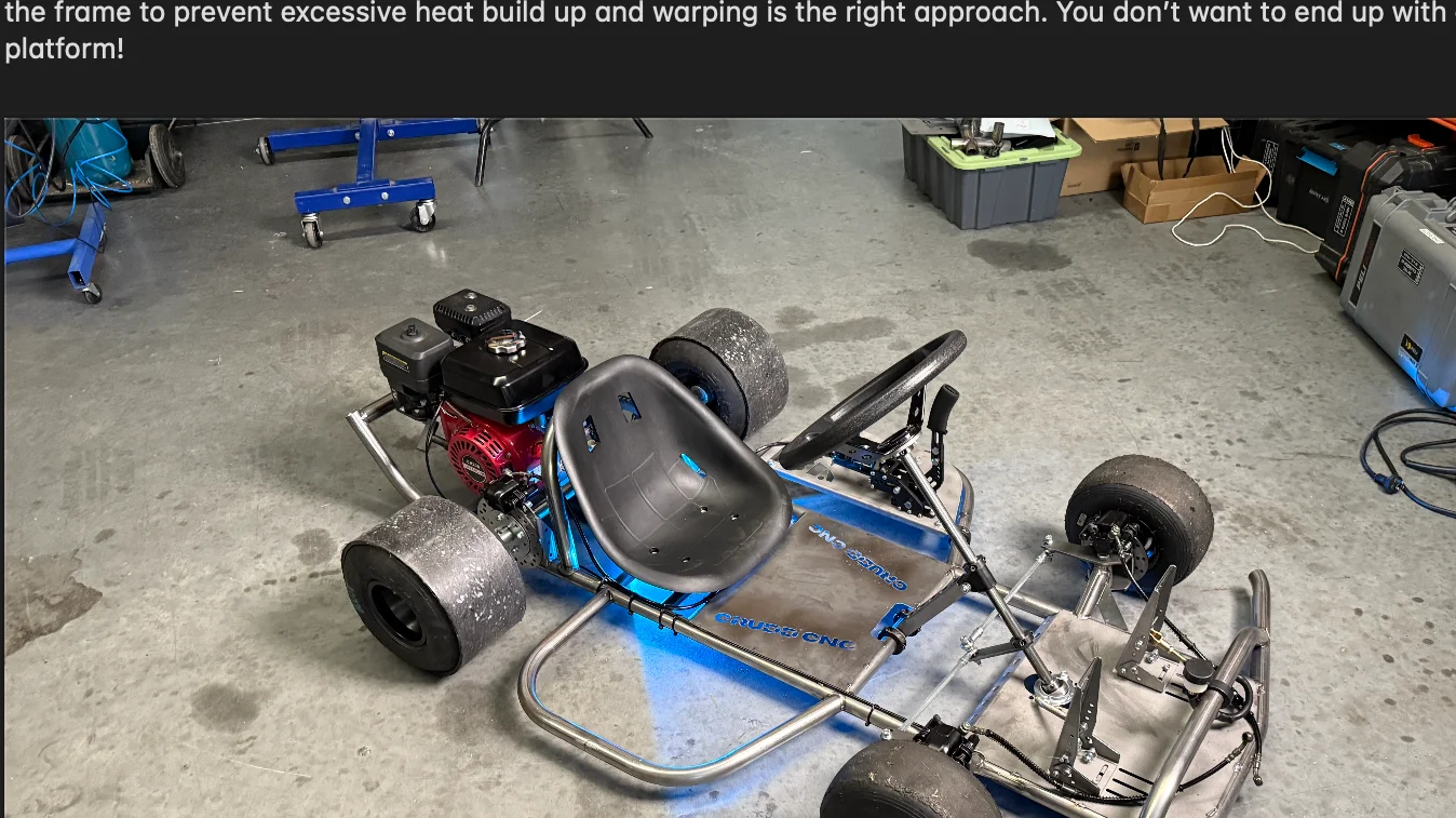
Paint, final assembly and drift sleeves
My frame had picked up some light surface corrosion while sitting for a couple of days, so I sanded and degreased it before painting. I used etch primer, epoxy enamel and a matte clear finish, following the products’ application instructions in a ventilated area protected from wind and dust.
Then came the satisfying part: putting it all back together. Starting with the rear axle made sense because access between the seat and engine was tight.
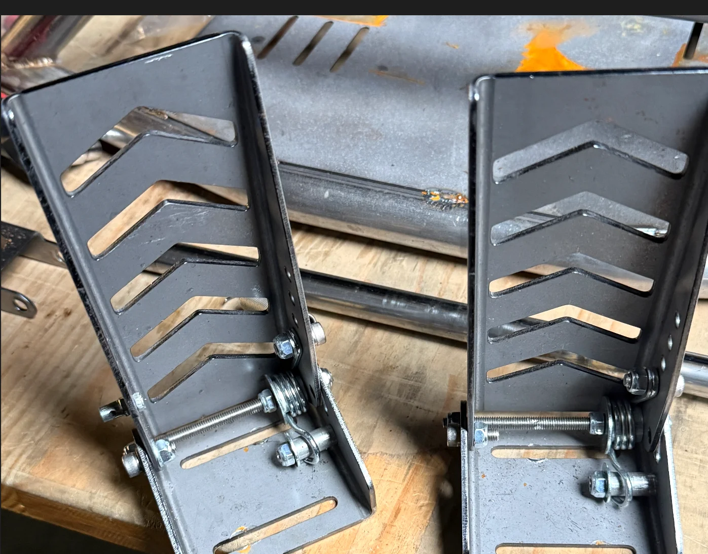
Final setup included checking chain tension, steering alignment, brakes and the throttle linkage. Those settings depend on the fitted components; follow their specifications, confirm that the throttle returns freely to idle and check the brakes before driving.
The rear drift sleeves took some patience to fit over the tyres. Sleeve fit and tyre pressure depend on the wheel, tyre and sleeve combination, so use the relevant component guidance rather than treating one pressure as suitable for every build.
After a final clean, the kart was ready for its next stage: driving and refining the build.
Watch the build
The workshop photos show the stages; the videos let you follow the work in more detail.
The CAD, drawings and parts list behind this kart
The Dad Drift Kart Builder Pack brings together the CAD, dimensioned drawings, fabrication files, templates, bill of materials and build notes.
US$149 for the digital package. Payment and file delivery are handled by Gumroad; your payment provider may apply currency conversion. Parts, tools and fabrication are separate.
Questions before buying? Ask me directly.